REC BMS SI Kit for SMA Sunny Island Inverter
We can ship worldwide and you can remove the 10% Australian GST that is included in our website prices. Please email info@solar4rvs.com.au for a product and shipping quote.
Items supplied as part of the basic product (without any of the additional cost options):
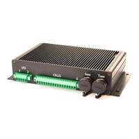
- REC Q 16S BMS Electronic unit for 5 to 16 cells
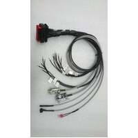
- Shunt sense cable (1 metre twin sheilded cable with 2 x 4mm eye lugs for Murata shunts. Note: lugs may also suit your existing shunt)
- Two temperature sensors each on 2metre shielded cable with one Dallas DS18B20 digital temperature sensor to measure battery temperature at two locations or measure battery and ambient temperatures (4 sensors, each on separate 2 metre cable into the one connector are in stock in Melbourne)
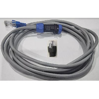
- CAN Bus cable (2metres length with DB9 connector to BMS and RJ45 connector to SMA inverter & 1 RJ45 connector with CAN Bus termination resistor)
- SMA firmware version installed (other versions can be downloaded & installed with either the Wifi unit (+ your phone/tablet/PC) or the REC PC software & galvanically isolated RS485 Cable.
BMS Features:
- BMS is preconfigured with firmware for connection to SMA inverters (normally 16 LFP cells)
- Also configurable by firmware version (which you can install via the Wi-Fi unit or the PC (Windows) app) - contact Solar 4 RVs if ever needed:
1) autonomous / standalone operation, or
2) operation with other inverters, eg. Victron Energy, Studer, Stecca Innotec, GoodWe, Solax, Solis, etc
- single cell voltage measurement (0.1 – 5.0 V, resolution 1 mV)
- single cell - under/over voltage protection
- single cell internal resistance measurement
- SOC (state of charge) calculation & time remaining
- SOH (state of health) calculation based on number of discharge cycles
- battery temperature sensor using
- over temperature protection (1 standard, but up to 3 temperature sensors with optional product)
- under & over temperature charging protection
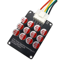
- cell balancing via 4.1 ohm resistors
- shunt current measurement (resolution 7.8 mA @ ± 200 A)
- 1 galvanically isolated user defined multi-purpose digital output
- internal relay (normally open)
- galvanically isolated RS-485 communication protocol
- CAN Bus communication (125 kbit, 250 kbit and 500 kbit)
- error LED + buzzer indicator
- hibernate switch
- BMS shutdown @ 0.98 x minimum cell disconnect threshold
- ISO16315, ISO10133, EN61558-1, EN61558-2 and EN50498 compliant
Latest BMS manuals are available on the REC BMS website: https://rec-bms.com/battery-management-system/
Refer to https://www.solar4rvs.com.au/batteries/lithium/bms/accessories-for-rec-bms/ to see details of other components that you might want for your REC BMS system.
General Description of the BMS Unit: The Battery Management System (BMS) monitors and controls each cell in the battery pack by measuring its parameters. The capacity of the battery pack differs from one cell to another and this increases with number of charging/discharging cycles. The Li-poly batteries are fully charged at typical cell voltage 4.16 - 4.20 V or 3.5 – 3.7 V for LiFePO4. Due to the different capacity this voltage is not reached at the same time for all cells in the pack. The lower the cell’s capacity the sooner this voltage is reached. When charging series connected cells with a single charger, voltage on some cells might be higher than the maximum allowed voltage. Overcharging the cell additionally lowers its capacity and number of charging cycles. The BMS equalizes cell’s voltage by diverting some of the charging current from higher voltage cells to power resistors – passive balancing. The device’s temperature is measured to protect the circuit from over-heating due to unexpected failure. Battery pack’s temperature is monitored by Dallas DS18B20 digital temperature sensor/s. Maximum 3 temperature sensors per unit may be used. Current is measured by a low-side shunt resistor. Battery pack current, temperature and cell’s voltage determine state of charge (SOC). State of health (SOH) is determined by comparing cell’s current parameters with the parameters of a new battery pack.
When connected by CAN Bus, the parameters that control the charging/discharging behaviour are calculated by the BMS each measurement cycle (1 second) and transmitted on the CAN Bus to the inverter. Near full and near discharged, the REC BMS will throttle back the permitted charge/discharge current and the inverter will follow the reduced limit.
(REC-SI-BMS-SMA-KIT)
| SKU | REC-SI-BMS-SMA-KIT |
1 year


