Comprehensive Flexible and Lightweight Solar Panel Mounting Instruction Guide
Author: Solar 4 RVs
SOLAR 4 RVS
FLEXIBLE SOLAR PANEL MOUNTING INSTRUCTION GUIDE
 Please read this document in full before commencing installation.
To maximise the efficiency and longevity of your new solar panels, please ensure you follow the instructions in this guide carefully. Failure to do so WILL result in shortened panel lifespan AND void your warranty.
While it seems simple to mount a flexible solar panel, common installations such as sealing around the edges of the solar panel and direct adhesion of the solar panel to a surface using Sikaflex and most other adhesives WILL damage the solar panel AND void your warranty, please continue reading the guide for more details.
Whilst due care has been taken to ensure these methods provide a secure and permanent mounting connection, we cannot guarantee these methods will be suitable in every scenario due to variations in substrate materials, environment, and installation technique. It is the duty of the purchaser to regularly inspect and maintain the solar panel installation.
It is normal for solar panels to heat up to above 85°C in operation or higher in fault conditions. In some cases, this can damage the substrate. The vented gap kit is recommended to avoid this. Solar 4 RVs will not be liable for any damage to the substrate the panels are installed onto.
If you need clarification on any of the instructions, please contact your distributor.
Contents
Protecting the panels during installation
INSTALLATION ONTO A RIGID SURFACE
STEP 1 Clean and degrease the surface area
STEP 2 Mark the position of panels accurately
STEP 3 Mount the panels using one of the following methods
Method 1 – Vented Gap Kit (Sunman eArc panels ONLY)
Method 2 – Solar 4 RVs 2.3mm VHB (Very High Bond) Tape or 3M 2.3mm 4991 Tape
Method 3 – Silicone Based Adhesives
Method 5 – Bi-Adhesive Backing
Method 6 – Onto Checker Plate (or other highly textured surfaces)
INSTALLATION ONTO ROOF RACKS (Sunman eArc panels ONLY)
Method 2 – Velcro (hook & loop)
Walking on the panels (Solbian anti-slip panels ONLY)
Protecting the panels during installation
IMPORTANT:
- All work should be carried out in shade or inside out of direct sunlight. Use a towel or blanket on top of the panel to reduce light exposure;
- Do not install the panels in windy or gusty conditions. Damage may result when handling or carrying a panel, or a gusty wind may lift and carry a lightweight panel;
- Do not damage the top layers or underside surfaces as the performance and longevity of the PV panel may be reduced if the surfaces are damaged;
- Do not store/stack other items underneath or on top of the panels;
- Avoid wearing sharp rings and jewellery during the installation;
- Avoid over-flexing the panels or repetitive flexing of panel;
- Avoid installing on a sunny day as adhesive/sealant can cure too quickly or surfaces, tools and the panel can become too hot for normal handling;
- Ensure the panels are fully supported, especially in the sun. A partially supported panel will get a permanent line crease between the supported and unsupported parts of the panel;
- If sharp or heavy objects are allowed to fall onto the panels, they can cause fractures in the cells;
Safety
- Work safely at heights. Ensure you have a sturdy, secure ladder;
- Use insulated tools;
- Ensure the panels are kept covered during installation;
.webp)
- Wear appropriate footwear;
- Use gloves and other PPE where appropriate;
- Seek help where needed.
Panel Curvature (Flexibility)
The panel can be curved with a gentle radius to a maximum mid-point deflection of approximately 100mm over a length of 1.5m.

There can only be one axis of bending in a panel; Longitudinal OR Transverse.
Longitudinal axis
The longitudinal bend can be convex as shown below.

Transverse axis
The image below shows a panel with multiple radii with all axis of rotation having the same direction, i.e. transverse with respect to the panel.

A real example of this is shown below
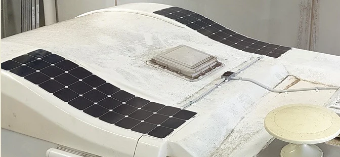
Multiple direction of axis
Panels cannot accommodate multiple radii with different directions without being stressed. For example, a longitudinal bend and a transverse bend.

Handling the Panel
Do not bend the panel excessively or repeatedly:
- The panels must not be bent more than 30 degrees per metre length, otherwise the cells and cell interconnections will be stressed;
- When being laid down both sides of the panel must be supported, either by sliding the panel along the surface or one person each side;
- Panels must not be laid on a surface with one or both ends hanging over an edge. The whole panel should be supported.
Do not stress the cells or junction box during handling
- Avoid carrying panels larger than 60W horizontally (like a tray) as they will droop;
- Carry the panel vertically along the long/side edge by gripping the panel along the edge white area of the panel (not putting pressure on the cells);
- Be careful not to apply excess pressure when holding the panel along the edge cells – being on the edge there is less support for these cells;
- Do not create localised stress on the cells between thumb and fingers which could cause fracturing of the cells;
- When lifting or laying the panel down, slide the far edge of the panel over the surface so that the panel is supported by your hands and the surface;
- The junction box and cables are not handles – do not hold the weight of the panel via the junction box.
INSTALLATION ONTO A RIGID SURFACE
If mounting your panel(s) onto a rigid surface such as a RV roof, you will need to take into consideration the thermal expansion and contraction of both the panel, the surface it’s being mounted to and the product used to adhere the two together. It is unlikely both the panel and surface will expand and contract at the same rate, therefore an adhesive with some ‘give’ will be required to absorb the difference.
|
UNSUITABLE Adhesive Products
|
SUITABLE Adhesive Products
|
|
|
*Solar 4 RVs has designed and recommends the Vented Gap Kit as the preferred installation method. This method not only allows for thermal expansion but also allows for air flow between the panel and mounting surface which keeps the temperature of both lower; increasing panel efficiency and protecting the mounting surface from heat related damage.
You will also need to consider if the mounting surface is suitable for the purpose.
|
UNSUITABLE Mounting Surfaces |
SUITABLE Mounting Surface: (using an approved mounting method) |
|
|
*Refer to Method 4 for Checker-plate.
STEP 1 Clean and degrease the surface area
To ensure proper adhesion, all surfaces (mounting surface, back of panel and strips if being used) must be cleaned and degreased. Not doing so will weaken the bond and can cause the bond to fail.
- Clean the surfaces with slightly soapy water to remove excess grime/dirt.
- Check the surface for any loose paint or blemishes, if required rub the mounting surface with a fine or medium grit emery.
- Use a suitable degreasing product such as industrial alcohol or isopropyl alcohol.
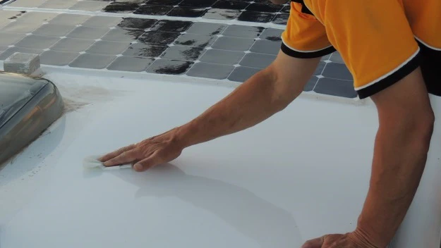
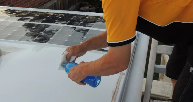
STEP 2 Mark the position of panels accurately
Check measurements and if needed, mark the position of the panels ensuring there is no overlap.
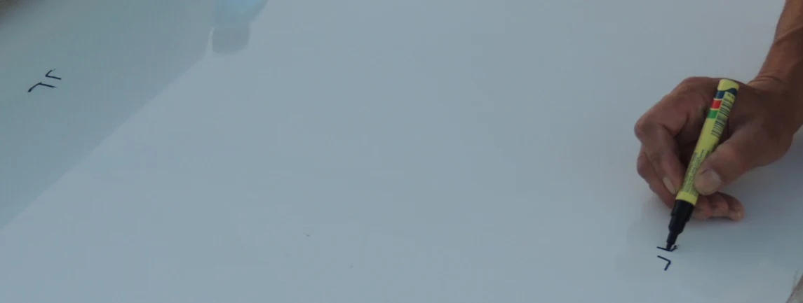
STEP 3 Mount the panels using one of the following methods
Method 1 – Vented Gap Kit (Sunman eArc panels ONLY)
The Vented Gap Kit is available exclusively from Solar 4 RVs and consists of pre-cut strips of twin-wall polycarbonate sheeting & VHB Tape.
How To:
Lay the panel face down on a soft surface (carpet, towel, etc.) and then line the strips into position. The strips have been pre-cut to fit along with width of the panel and should be positioned so that each strip runs in between each row of cells (approx. 160mm) with the exception of the ends of the panel which have 2 strips each. Use a pencil or pen to mark where the strips will sit.
NOTE: Now that many panels use cut cells, the spacing may need to be every 2 or 3 cut cells to make the approx. 160mm distance. Normally panels 175W to 215W will use 12 strips, 4 at the ends, the 8 distributed along the middle. 100W panels will use 9 strips.
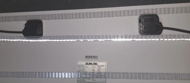
Top of panel with ‘Junction Box Under’ - Position strips around the junction box. Different panels will have slightly different junction boxes, but the principle remains the same.
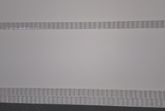
Top of panel with ‘Junction Box on Top’ – Position 2 strips at the top, then 1 strip every cell gap width for the remainder of the panel.
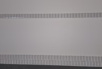 Bottom of panel (regardless of junction box position).
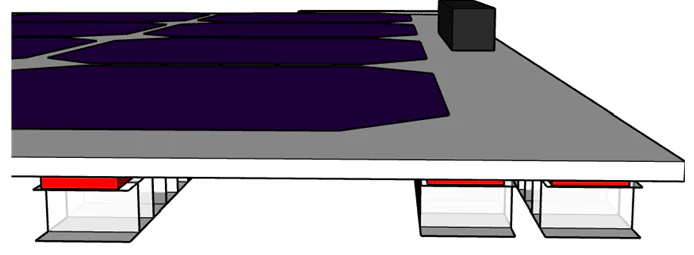
Side view of panel with panel, showing double strips at top.
If your panel has the Junction Box on Top - Apply double-sided acrylic high bond foam tape to both sides of the strips and attach to the panel (leave the top layer of red plastic intact for now). Finger pressure must be used to push the tape into the surface to make sure that it has sufficient grip on the surface for adequate bond strength.
If your panel has the Junction Box Under - Apply double-sided acrylic high bond foam tape to both sides of the strips. You will need to use extra layers of tape to build up the area in which the junction box sits. Do this by applying up to 2 layers of tape on each side of the strip (4 layers of tape total per strip near the junction box). The tape will bond together. Once done, attach the strips to the panel (leave the top layer of red plastic intact for now).

Double layer of tape.
Once the strips are attached to the panel, proceed to carefully lay the panel into position and remove the red plastic layer. Gently apply pressure in between the cells, along the strips, ideally with a roller. Ensure you do not apply excessive force or push on the cells where there is no strip behind as this will damage the cell.
Wait time of tape to full strength:
20 minutes – 50% strength
1 hour – 75% strength
1 day – 90% strength
3 days – 100% strength
Method 2 – Solar 4 RVs 2.3mm VHB (Very High Bond) Tape or 3M 2.3mm 4991 Tape
Both above-mentioned tapes have been tested by Solar 4 RVs and deemed suitable for use in mounting our solar panels. Any other brand of tape should not be used unless prior approval has been given.
Follow the instructions in Method 1, ignoring any mention of the plastic strips.
Method 3 – Silicone Based Adhesives
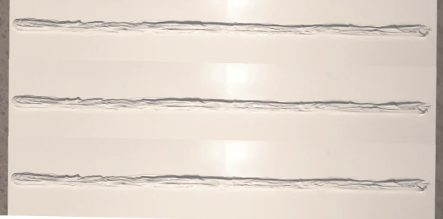
If using a Silicon based adhesive such as SG20 or Fix8, apply the product in strips running the width of the panel underneath each cell gap.
Do not seal around the edge of the panel as this will trap air under the panel which will expand as the panel heats up, causing damage to both the panel & mounting surface.
Method 5 – Bi-Adhesive Backing
Bi-Adhesive backing is available for purchase with your panels. This method is required if you plan to walk on your panel (please read Walking on the panels for greater detail). This method is an easy ‘peel and stick’ method, however, be mindful not to over-flex the panel in the process.
While the durability of the Sunman eArc panels is unmatched, they are not designed to be anti-slip, and therefore walking on is not recommended
Method 6 – Onto Checker Plate (or other highly textured surfaces)
High bond tape does not bond well to checker plate and there are very few adhesives suitable for polycarbonate (i.e. The strips in our vented gap kit). Some adhesives may appear to bond well at the start but then lose adhesion over time. For these reasons, we recommend that another medium such as aluminium composite (as a sheet or cut into strips) be used in between the checker plate and tape. Attach the aluminium to the checker plate with screws, pot rivets or a suitable adhesive then use of one of our standard mounting methods to mount the panel to the aluminium.
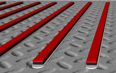

The bond area of the roof should be well drained, i.e. panels should not be bonded where water can puddle. Any droops in the surface should be fixed first.
Other textured surfaces may not be suitable for tape and require the use of this method.
INSTALLATION ONTO ROOF RACKS (Sunman eArc panels ONLY)
If mounting on a roof rack where there is no way to support the edge of the panel, Sunman eArc panels can be stiffened by the use of C channel to the edges, and flat bar between the front and back of the panel, this additionally provides edge protection on the front and rear ends of the panel.
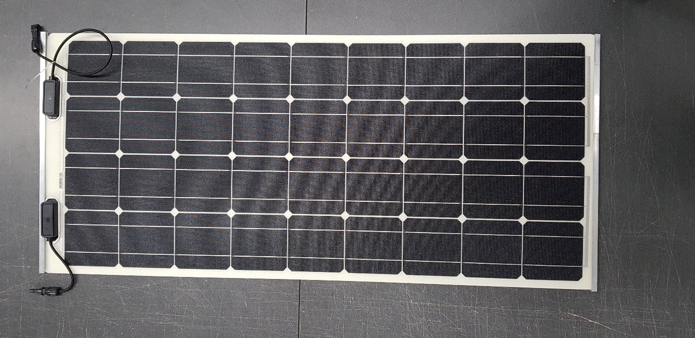
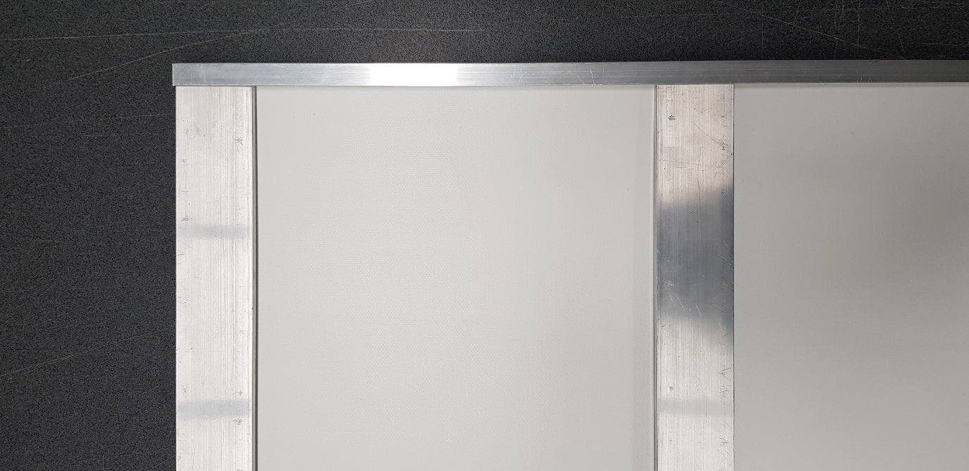
The flat bar is fixed to the panel using appropriate very high bond tape – if required the bar can protrude past the panel to line up with the roof racks to avoid the need to drill through the panel. The C channel slots onto the panel and flat bar and it is secured using Fix8 injected into the C channel.
The panel can be fixed to the roof rack using bolts and/or screws on the exposed aluminium section. Alternatively eyelets can be fitted at the point of sale for fixing.
INSTALLATION ONTO CANVAS
Panels can be attached to canvas providing the following guidelines are carefully adhered to:
- The canvas must provide continuous support to the panel
- Shallow radius, i.e. do not bend panel excessively
- The panel is not laid over irregularities such as structural elements, e.g. ridges/beams/tubes. These will result in the panel creasing over the structure causing premature failure.
- Panels shall not be placed over tubes supporting the canvas
- The canvas shall provide continuous support for the panel
- No part of the installed panel shall be bent by more than 10 degrees per metre length
- Panels shall not be placed onto a canvas surface where there are multiple radii with
- different axes.
- The canvas shall be kept taut
- No part of the panel shall be covered with any form of transparent material
See Example of good installs for images.
Method 1 – Zippers
Zippers along each long edge can be used. These are sewn under the panel so that the zip material provides a cushion against the edge of the panel.
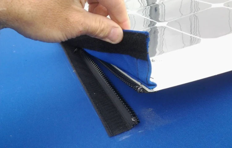
This image demonstrates the zipper method along with good execution of a cover over the edge of panel and zip.
A canvas makers standard industrial machine is adequate to sew zips onto the panel. You will need to provide the following instructions to your canvas maker:
- Use a YKK Marine rated zipper, UV resistant with auto locking slider
- Use a course stitch of at most 5-6 threads per inch
- Use polyester or PTFE based thread
- Attach zips in opposite directions so the sliders are at opposite corners of the panel
Method 2 – Velcro (hook & loop)
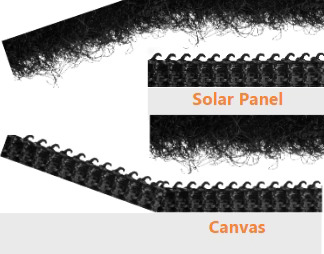
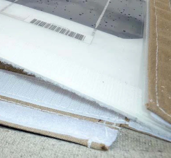
Velcro must be attached under and over the panel so that the panel is in the “middle of a
Velcro sandwich”. Velcro is not recommended as on removal of the panel, excessive force may damage the cells compared to Zips where to force is put onto the cells during removal.
Method 3 – 3M Dual Lock
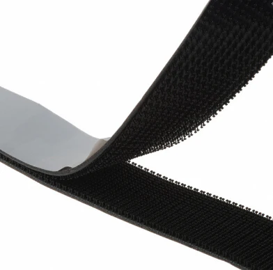 Dual lock can be used as an alternative to Velcro using the same instructions.
Method 4 - Loxx Fasteners
Loxx fasteners can be used to attach panels to canvas or other material. Enough fasteners must be attached alongside each panel edge to fully support the panel. The size of panel will determine the adequate number of fasteners. Speak to our technicians to confirm based on the panel you’ve purchased.

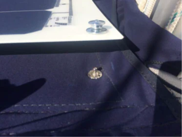
Method 5 – Eyelets
Solar 4 RVs can punch stainless steel eyelets into the panel at various intervals (please advise at time of purchase) along the panel. Rope or similar material can then be used to tie the panel down to a supported surface.
Enough eyelets must be attached alongside each panel edge to fully support the panel. The size of panel will determine the adequate number of eyelets. Speak to our technicians to confirm based on the panel you’ve purchased.

Combination of eyelets & Rope.
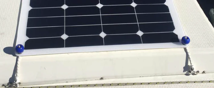
Combination of eyelets, rope & rope clamp.
Example of good installs
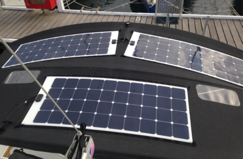
o Panels are well supported by the canvas over the entire back surface of the panel
o Panels are well clear of the transverse beams
o Slight bending of panel in one axis
o Similar sun strength on all cells and panels as curvature is slight
o Cables are not applying any lifting, shear or twisting force on the junction box, i.e.
o cables are laid neatly, level and are gently radiused.
o Custom “sewn-in conduit” keeps cables neat
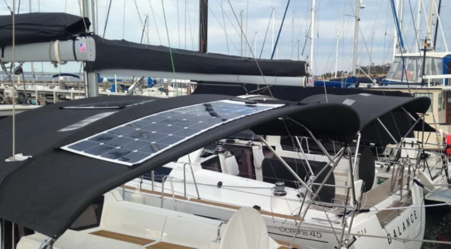
o End of panel is well clear of the sharp roll-off at the side of the bimini
o Canvas is taut which is essential to avoid “flapping” induced mechanical stress on the panel
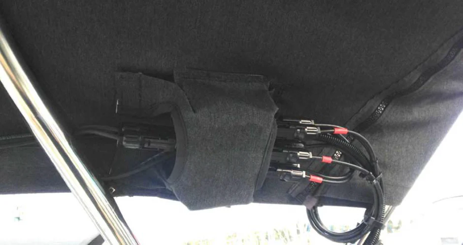
o Custom pocket houses a polycarbonate enclosure containing 3 fuses
o Underside location avoids rain/seawater directly on the IP67 solar connectors
o Panels can be easily removed as connectors are used
Example of bad installs
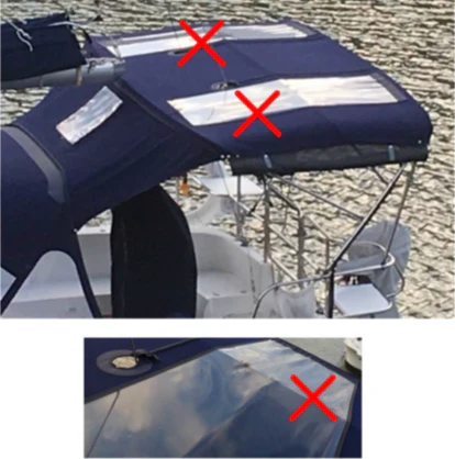
o Panels have an obvious crease which will cause stress on the cells
o Plastic cover over panels traps excess heat and moisture
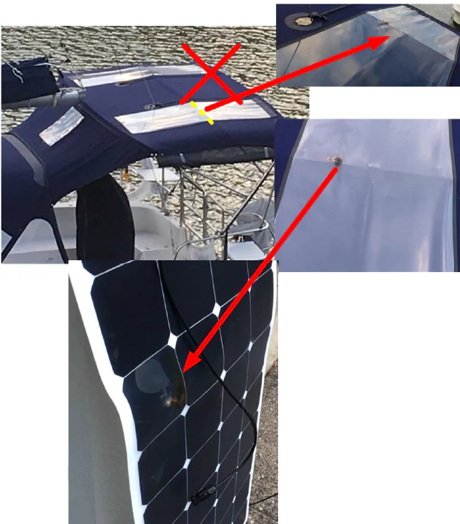
In this example, the bending over the tube lead to fracturing of the cells and produced a hot spot within months of installation.
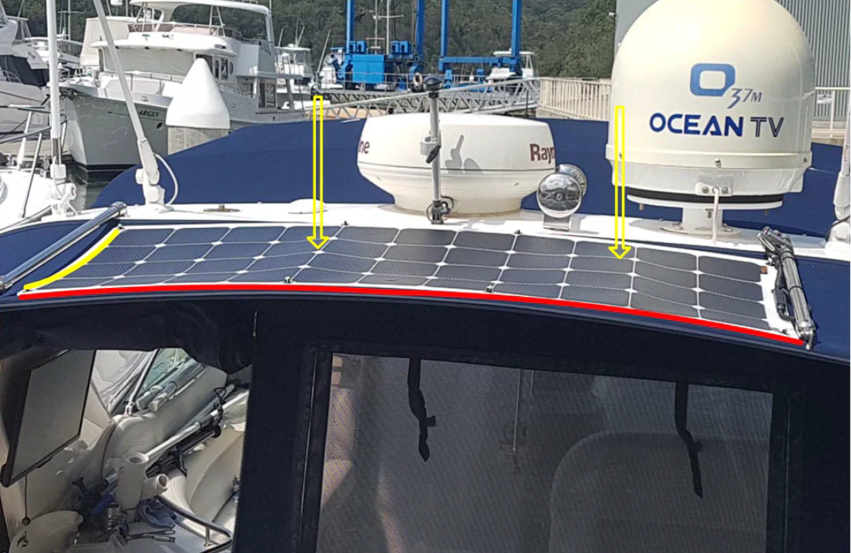
x Panels have an obvious crease which will cause stress on the cells
x Panels are flexing in multiple directions causing increased stress on the cells
Walking on the panels (Solbian anti-slip panels ONLY)
Solbian anti-slip surface panels are the only panels sold by Solar 4 RVs that allow the panel to be walked on, provided they are installed in the following manner:
- using bi-adhesive backing;
- onto flat, smooth, continuous surface (no bumps, hollows or irregularities).
Panels must only be walked on by people taking care whilst barefoot or wearing flat, soft-soled shoes. Heels or shoes with a rigid sole will cause damage to the panel.
Uninstalled panels or panels in removable installations (using eyelets etc.) must not be walked on.
Walking on panels should be avoided, only walk on the panels when necessary.
Maintenance
To ensure your solar panels are performing optimally, be sure to keep on top of this simple maintenance checklist.
- Clean on a regular basis with neutral soap & clean water, using a soft sponge or cloth;
- If in a marine environment, wash regularly with fresh water to avoid damage caused by saltwater;
- Periodically inspect the mechanical and electrical connections;
- Denatured alcohol (methylated spirit) can be used to remove grease etc.
Ongoing Support
Solar 4 RVs are proud to offer a support service beyond the purchase of your solar panels. If you require further technical support, please feel free to contact us. We are happy to help!


