Choosing the Right Solar Charge Controller/Regulator
Author: Solar 4 RVs
Why Do I Need a Solar Charge Controller?
A solar charge controller (frequently called a regulator) is similar to a regular battery charger, i.e. it regulates the current flowing from the solar panel into the battery bank to avoid overcharging the batteries. (If you don't need to understand the why's, scroll to the end for a simple flow chart). As with a regular quality battery charger, various battery types are accommodated, the absorption voltage, float voltage can be selectable, and sometimes the time periods and/or the tail current are also selectable. They are especially suited for lithium-iron-phosphate batteries as once fully charged the controller then stays at the set float or holding voltage of around 13.6V (3.4V per cell) for the remainder of the day.
The most common charge profile is the same basic sequence used on a quality mains charger, i.e. bulk mode > absorption mode > float mode. Entry into bulk charge mode occurs at:
- sunrise in the morning
- if the battery voltage drops below a defined voltage for more than a set time period, e.g. 5 seconds (re-entry)
This re-entry into bulk mode works well with lead-acid batteries as the voltage drop and droop is worse than it is for lithium-based batteries which maintain a higher more stable voltage throughout the majority of the discharge cycle.
Lithium Batteries
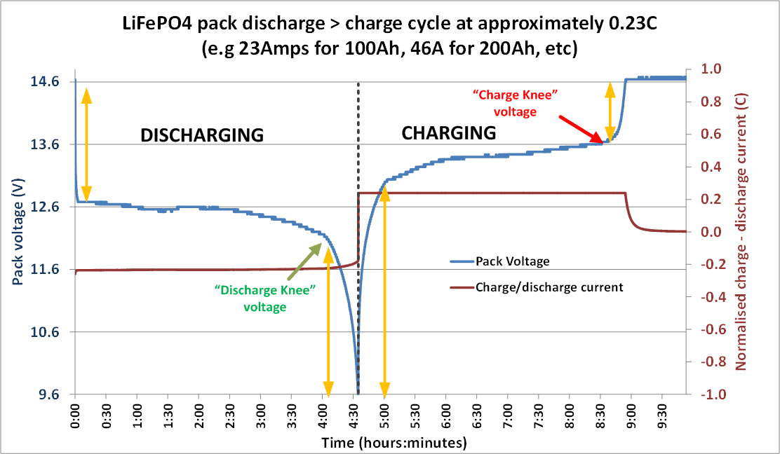
Lithium batteries (LiFePO4) do not benefit from re-entry into a bulk mode during the day as the internal impedance of the lithium batteries increases at high (and low) states of charge as indicated by the orange vertical lines in the chart below and it is only necessary to occasionally balance the cells which can only be done around the absorption voltage. A related reason is to avoid the rapid and large variation in voltage that will occur in these regions as large loads are switched on and off.
Lithium batteries do not have a defined “float voltage”, and therefore the “float voltage” of the controller should be set to be at or just below the “charge knee voltage” (as indicated in the chart below) of the LiFePO4 charge profile, i.e. 3.4V per cell or 13.6V for a 12V battery. The controller should hold this voltage for the remainder of the day after bulk charging the battery.
The Difference Between PWM and MPPT Solar Charge Controllers
The crux of the difference is:
- With a PWM controller, the current is drawn out of the panel at just above the battery voltage, whereas
- With an MPPT solar charge controller the current is drawn out of the panel at the panel “maximum power voltage” (think of an MPPT controller as being a “smart DC-DC converter”)
You often see slogans such as “you will get 20% or more energy harvesting from an MPPT controller”. This extra actually varies significantly and the following is a comparison assuming the panel is in full sun and the controller is in bulk charge mode. Ignoring voltage drops and using a simple panel and simple math as an example:
- Panel maximum power current (Imp) = 5.0A
- Panel maximum power voltage (Vmp) = 18V
Battery voltage = 13V (battery voltage can vary between say 10.8V fully discharged and 14.4V during absorption charge mode). At 13V the panel amps will be slightly higher than the maximum power amps, say 5.2A
With a PWM controller, the power drawn from the panel is 5.2A * 13V = 67.6 watts. This amount of power will be drawn regardless of the temperature of the panel, provided that the panel voltage remains above the battery voltage.
With an MPPT controller the power from the panel is 5.0A * 18V = 90 watts, i.e. 25% higher. However this is overly optimistic as the voltage drops as temperature increases; so assuming the panel temperature rises to say 30°C above the standard test conditions (STC) temperature of 25°C and the voltage drops by 4% for every 10°C, i.e. total of 12% then the power drawn by the MPPT will be 5A * 15.84V = 79.2W i.e. 17.2% more power than the PWM controller.
In summary, there is an increase in energy harvesting with the MPPT controllers, but the percentage increase in harvesting varies significantly over the course of a day.
The Differences in PWM and MPPT Operation:
PWM:
A PWM (pulse width modulation) controller can be thought of as an (electronic) switch between the solar panels and the battery:
- The switch is ON when the charger mode is in bulk charge mode
- The switch is “flicked” ON and OFF as needed (pulse width modulated) to hold the battery voltage at the absorption voltage
- The switch is OFF at the end of absorption while the battery voltage drops to the float voltage
- The switch is once again “flicked” ON and OFF as needed (pulse width modulated) to hold the battery voltage at the float voltage
Note that when the switch is OFF the panel voltage will be at the open-circuit voltage (Voc) and when the switch is ON the panel voltage will be at the battery voltage + voltage drops between the panel and the controller.
The best panel match for a PWM controller:
The best panel match for a PWM controller is a panel with a voltage that is just sufficiently above that required for charging the battery and taking temperature into account, typically, a panel with a Vmp (maximum power voltage) of around 18V to charge a 12V battery. These are frequently referred to as a 12V panel even though they have a Vmp of around 18V.
MPPT:
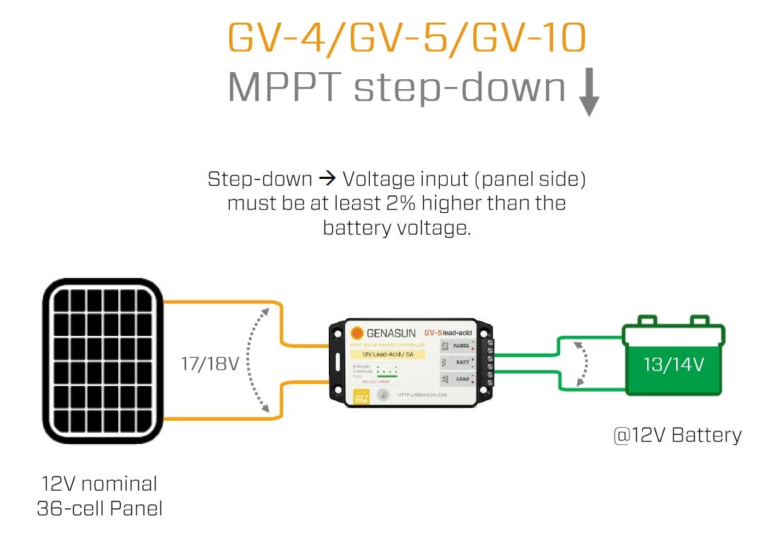
The MPPT controller could be considered to be a “smart DC-DC converter”, i.e. it drops the panel voltage (hence “house panels” could be used) down to the voltage required to charge the battery. The current is increased in the same ratio as the voltage is dropped (ignoring heating losses in the electronics), just like a conventional step-down DC-DC converter.
The “smart” element in the DC-DC converter is the monitoring of the maximum power point of the panel which will vary during the day with the sun strength and angle, panel temperature, shading, and panel(s) health. The “smarts” then adjust the input voltage of the DC-DC converter – in “engineering speak” it provides a matched load to the panel.
The best panel match for an MPPT controller:
- The panel open circuit voltage (Voc) must be under the permitted voltage.
- The VOC must be above the “start voltage” for the controller to “kick in”
- The maximum panel short circuit current (Isc) must be within the range specified
- The maximum array wattage - some controllers allow this to be “over-sized”, e.g the Redarc Manager 30 is permitted to have up to 520W attached
Choosing the Right Solar Controller/Regulator
The PWM is a Good Low-Cost Option:
- for smaller systems
- where the efficiency of the system is not critical, e.g trickle charging
- or solar panels with a maximum power voltage (Vmp) of up to 18V for charging a 12V battery (36V for 24V battery, etc).
The MPPT Controller is Best:
- For larger systems
- where the additional 20%* or more energy harvesting is worthwhile
- When the solar array voltage is substantially higher than the battery voltage e.g. using house panels, for charging 12V batteries
*An MPPT controller will yield higher returns compared with a PWM controller as the panel voltage increases. I.e. a 160W panel using 36 conventional monocrystalline cells with a maximum power amp of 8.4A will provide around 8.6A at 12V; while the 180W panel having 4 more cells will provide the same amperage but 4 additional cells increases the panel voltage by 2V. A PWM controller will not harvest any additional energy, but an MPPT controller will harvest an additional 11.1% (4 / 36) from the 180W panel. For the same principle, all panels using SunPower cells with more than 32 cells require an MPPT charge controller otherwise a PWM controller will harvest the same energy from 36, 40, 44 cell panels as it does from a 32 cell panel.
Solar Charge Controller Features and Options
Victron SmartSolar Controllers have a built-in Bluetooth to monitor your MPPT remotely by pairing it with a smartphone or other device through the Victron app.
Boost MPPT Controllers
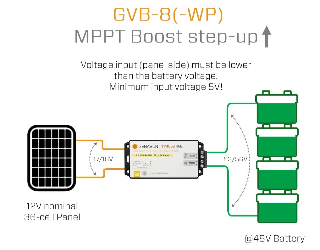
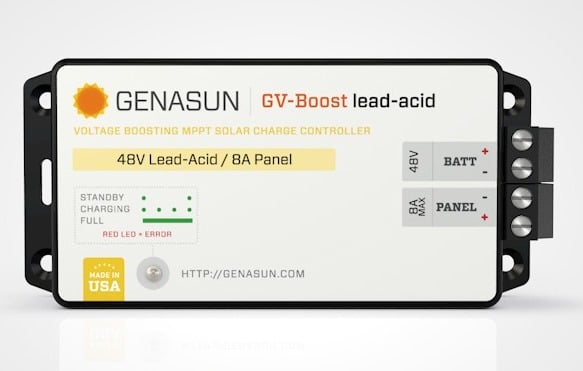
“Boost” MPPT charge controllers allow batteries to be charged that has a higher voltage than the panel.
Combined MPPT and DC-DC Chargers
The MPPT function is a natural adjunct to the DC-DC charger function and there are several quality brands that provide this with more under development.
A single unit can be used by itself, as it automatically switches between alternator charging and solar charging. For larger systems, our favoured arrangement is to use a separate MPPT controller for the fixed roof-mounted panels and use the combined MPPT/DC-DC with portable panels. In this case, an Anderson connector is placed on the exterior of an RV which is then wired to the solar input of the MPPT/DC-DC unit.
Note that the battery capacity must be sufficient so that the combined charging current from simultaneous charging from the alternator and the roof solar panels does not exceed the manufacturer's recommended maximum charging current.
Cheaper Options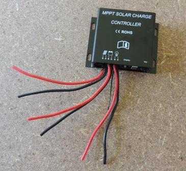
Cheap controllers may be marked as an MPPT but testing has shown that some are in fact PWM controllers.
Cheap controllers may not have the over-voltage battery protection which could result in the battery being overcharged with potential damage to the battery; caution is recommended. Normally, due to the increased circuitry, MPPT solar charge controllers will be physically larger than PWM solar charge controllers.
Multiple Solar Chargers
Properly wired, it is possible to add multiple solar chargers (any combination of type and rating) to charge a battery. Proper wiring means that each solar charger is wired separately and directly to the battery terminals. This ideal case means that each controller will “see” the battery voltage and is unaffected by the current flow coming from other charge controllers. This situation is no different from charging a battery from the grid/generator at the same time as charging from solar. With modern controllers, the current will not flow backwards from the battery to the controller (excepting a very small quiescent current).


